In many circumstances it is desirable to work with an 8 pin serial eeprom or Motorola microcontroller while it remains connected to the circuit assembly. The less desirable task of completely unsoldering the part from the board so that it can be attached to the programming instrument is far more likely to cause problems. Issues such as chip damage due to heat, lifting a board trace or dislodging of near by surface mount components all make chip removal a far more risky process. Cleaning the chip pins and attaching a
clip or probes to the in-circuit part allows for a faster, safer procedure with much less risk of assembly damage.
THE CHALLENGES OF IN-CIRCUIT READING AND PROGRAMMING
In-circuit access to an 8 pin serial eeprom or microcontroller poses a challenge to product designers as the part is not only soldered to the circuit assembly but is also connected to existing components on the assembly itself. The challenge is to make the part appear to the programming instrument as though it is an unconnected device. In other words make a part which is already connected to other components look like it is not.
Andromeda Research products are designed to work with eeproms and microcontrollers in-circuit. The
AR-32A programming instrument, when used with
adapters specifically designed for in-circuit work, provides the best opportunity for successful part communication without removal from the assembly. Andromeda Research is know for providing an excellent in-circuit reading and programming solution for applications where unsoldering the part from the circuit assembly is not the desired approach. (
read customer comment)
OBSTACLES TO SUCCESS - There are two primary obstacles or conditions which can interfere with successful in-circuit eeprom work. These are existing circuit loading and existing circuit activity.
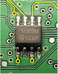
EXISTING CIRCUIT LOADING -
The part shown in the photo on the right is a 95320 serial eeprom. The hi-lited (yellow) circuit traces show how the part is connected to other components on the assembly. When the programming instrument is attached to the part and instructed to read the data two fundamental conditions must occur. First the part must have power applied in order to operate. Second, each pin on the part which is required for successful communication must be driven to a valid logic level while the part is being read. A logic level is the voltage necessary for the part to interpret the applied signal as a logic 0 (low) or logic 1 (high). If the part does not see a valid logic level on all pins necessary for communication then the part will not respond. The programming instrument must have sufficient drive capability to overcome the load presented by the existing module circuitry (yellow traces) to allow the application of valid logic levels.
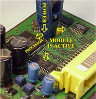
EXISTING CIRCUIT ACTIVITY -
The second condition which affects successful in-circuit programming is caused by power backfeeding into the circuit assembly. The backfeed occurs because the power pins on the chip to which the programming unit is connected are also connected to the common power bus which feeds the entire module circuit assembly. If the power (voltage) applied to the eeprom chip is the same level as the standard assembly operating voltage, then the entire module will power up and become active (see photo right). When this happens the processor (microcontroller) will begin communicating with the eeprom at the same time the programming instrument is attempting to read data from the chip. The resulting data collision causes invalid or incorrect data to be read by the programming instrument. Also, in some cases, the collision can cause data corruption within the eeprom itself as the chip is trying to process and respond to commands from two different sources (processor and programmer).
ADDRESSING IN-CIRCUIT OBSTACLES
CIRCUIT LOADING -
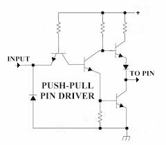
The issue of circuit loading is addressed by incorporating push-pull pin driver circuitry in the programming instrument and adapters. A push-pull pin driver operates by forcing current to flow in both directions (in and out) with respect to the target pin and desired logic level. The driver circuit incorporates a two transistor output stage where the top transistor will source (push) a positive current into the device pin for a logic 1 (high). For a logic 0 the bottom transistor will conduct and (sink or pull) current from the device pin forcing it to a low voltage level. Because there are individual transistors dedicated to driving the device pin to each logic level, a push-pull driver provides the best opportunity to overcome a pin load due to the pin being connected to existing components on the assembly. Also, due to the design of the push-pull circuit, the driver will limit the current applied to the pin to a level which prevents the attached circuitry and programming unit from being damaged.
CIRCUIT ACTIVITY -
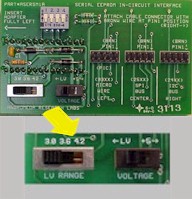
The issue of power backfeeding into the circuit which causes the entire assembly to become active is addressed with a special adaper which incorporates a variable voltage power selector. The
ASERSM1A in-circuit serial eeprom adapter allows the voltage which is applied to the assembly to be reduced when the eeprom is read or programmed. This is accomplished using two switches; VOLTAGE (LV-5V) and LV RANGE (3.0-3.6-4.2). Reducing the operating voltage to the assembly has two effects. The first is that the other components on the assembly, even though active, will present a reduced load. This is because there is less current available to interfere with reading and programming the eeprom in-circuit allowing the push-pull driver to be more effective. The second is that the microcontroller (processor), which will normally start accessing the eeprom when the power is applied to the assembly, will not start at a reduced voltage. This means that invalid data resulting from processor interference does not occur. Using the voltage reduction technique provides excellent results when reading or programming eeproms in-circuit.
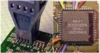
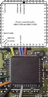
WORKING WITH MICROCONTROLLERS IN-CIRCUIT - Microcontrollers present a similar but somewhat different challenge as compared to in-circuit work with eeproms. First, unlike the eeprom, microcontrollers cannot be operated at a reduced voltage. A microcontroller must operate at its specified voltage (usually 5 volts) to function properly. In its normal operating mode the microcontroller performs the functions for which it was programmed (airbag module, digital cluster, immobilizer, etc.). This is the program that it runs when the module starts. When in-circuit reading and programming of a microcontroller is desired, the microcontroller must NOT run its standard program. It must run another program (special communication) or enter a mode which will allow the programming instrument to communicate with the microcontroller itself. This is much like a modem link between two computers except in this case it is between the programming instrument and the microcontroller. In order for the microcontroller to enter the special communication mode certain pins (pin numbers) on the chip itself must be preset to specific logic or voltage levels. Once the preset levels are established, the microcontroller will be reset by the programming instrument. When the microcontroller exits the reset condition it will test the logic state on the pins. Based on the pin logic levels the microcontroller will either run its standard program or enter the special communication mode. The illustration on the right shows a Motorola 68HC11E9 microcontroller. You can see from the top illustration the power pins (1 and 26), the communication pins (20 and 21), the reset pin (17), the clock input pin (7) and the mode pins (2 and 3). The logic levels on the mode pins determine which program the microcontroller will run after the part is reset. The lower photo shows the probes physically connected to the part. In most cases connecting to the microcontroller is simply a matter of attaching the correct probes to the proper pins on the part. If, however, a pin on the part cannot be driven to the required logic level, the microcontroller will not run the communication program or enter the communication mode.
TIPS AND TOOLS FOR IN-CIRCUIT MICROCONTROLLER WORK
The pin connections on a microcontroller are subject to the same loading conditions which affect eeproms when working in-circuit. The microcontroller adapter (
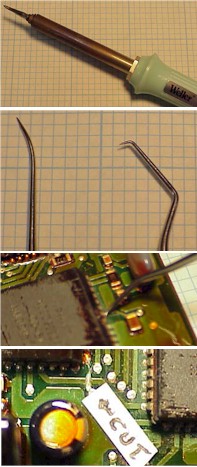
ACOM2) is designed with push-pull drivers which provide the best opportunity for successful in-circuit work. A condition which can occur with a microcontroller is that a pin which defines the chip operating mode (standard program or communication program) may be attached to an assembly power rail (directly to the power supply track). If the module design engineer chose to connect the pin directly to the power supply to present the desired logic level to the part, but the opposite logic level must be applied in order to enter communication mode, it is possible that a "short-circuit" will result. In other words if a logic 1 (5 volts) is required for the standard program to run and a logic 0 (ground) is required for communication mode, when you attach the probe which forces the logic 0 on the pin you connect ground to 5 volts which creates a short. This does not damage the programming instrument or the part however it obviously will not allow the part to work. In this case the offending pin must be isolated from the assembly circuitry (disconnected from the board) in order for in-circuit work to be successful. There are two techniques for isolating (disconnecting) a microcontroller pin which cannot be driven or forced to the required logic level. The first is to heat the pin with a low wattage soldering iron (top photo) until the solder melts. Once the solder is molten place a sharp object such as a dental pick (second photo) or x-acto knife blade behind the pin and carefully lever it up (about 45 degrees) or until the connection between the pin and assembly pad is open. Once the pin is free connect the probe and perform your work. After you are finished bend the pin down until it contacts the pad then apply heat from the soldering iron. You may need to apply a small amount of solder. The second technique is to cut the track which connects to the pin. This only works if the pin is connected to a single track. If the track continues under the chip this will not work. To cut the track use an x-acto knife or other sharp object and very carefully cut across the width of the trace until there is a clear opening in the conductor. You can confirm that the trace is open using an ohm meter or the LP-1 (see below). After you have performed your work carefully scrape the solder mask from each side of the cut then apply a small amount of solder across the cut to create a solder bridge. This reestablishes the connection.
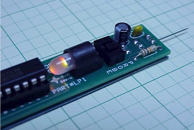
LOGIC/TEST PROBE -
The LP-1 Logic/Test probe is a tool designed to identify in-circuit programming issues before communication problems occur. The LP-1 allows you to determine if a pin on the target device can be driven to valid logic levels before you connect the programming instrument. This not only saves time but also eliminates the need to guess which pin to lift if communication is not successful. Use of the LP-1 also prevents the possibility of grounding a mode pin which may short out the power connection. The LP-1 works by injecting the same drive signal into the target device pin (microcontroller or eeprom) as is used by the programming instrument. If the LP-1 cannot drive the pin the LED indicator on the probe will stop flashing and lock at one level. This indicates to you that the pin must be lifted. The LP-1 will also work (test mode) as a standard logic probe. In this mode the probe will indicate the logic level (high or low) on a specific pin. (
LP-1 information is here)